This How-to will give you a step-by-step guide on how to integrate the Wheel Drive Unit (DR1N) from the Robotics Kit ROKIT in the FSoE EtherCat Network of a ctrlX CORE with ctrlX SAFETY
Versions Used and Required Software
ctrlX OS 3.6
Elmo Application Studio EAS 2.9
XML Device Description for ELMO Platinum
ctrlX SAFETY Engineering 1.8.3.10207
ctrlX Apps from ctrlX OS Store
HW Setup & Prerequisites
ctrlX CORE Device (X3, X5, X7) + Power Supply
ctrlX SAFETY Safex Device (C.12, C.15) + Power Supply + Emergency Stop
Wheel Drive Unit (DR1N) + Power Supply + HW STO
Wheel Drive Unit parametrized for HW STO and in Remote Mode (EASII)
PC with the above-mentioned Software installed
Successfull finished the first How To on the Wheel Drive Unit
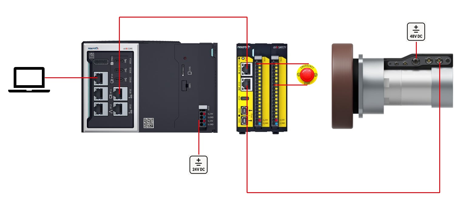
Important Hint Regarding Safety Systems
In safety systems, all configurations must match each other exactly. The system will only work when the changes are made consistently in the Elmo Settings, the ctrlX SAFETY Engineering and the ctrlX I/O Engineering.
Step-by-Step guide
1. Add the SAFEX to the EtherCat Master in ctrlX I/O Engineering
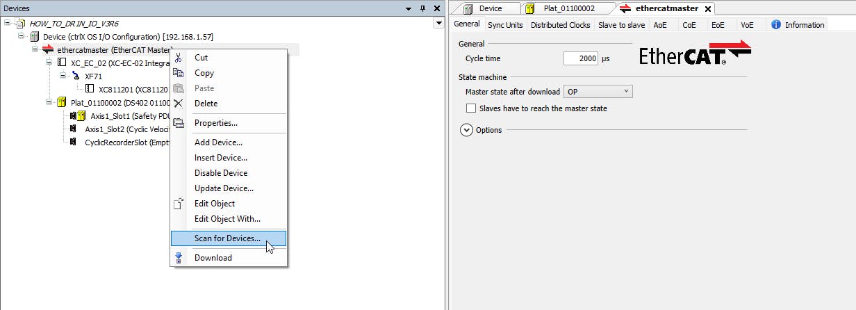
1.1 Open ctrlX I/O Engineering, right-click on "ethercatmaster" and "Scan for Devices..." and add the SAFEX to the Project.
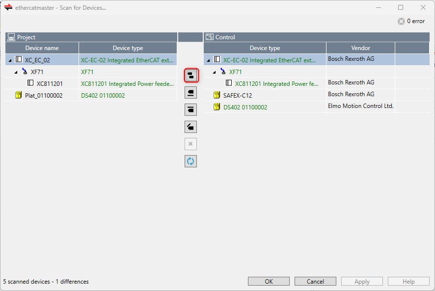
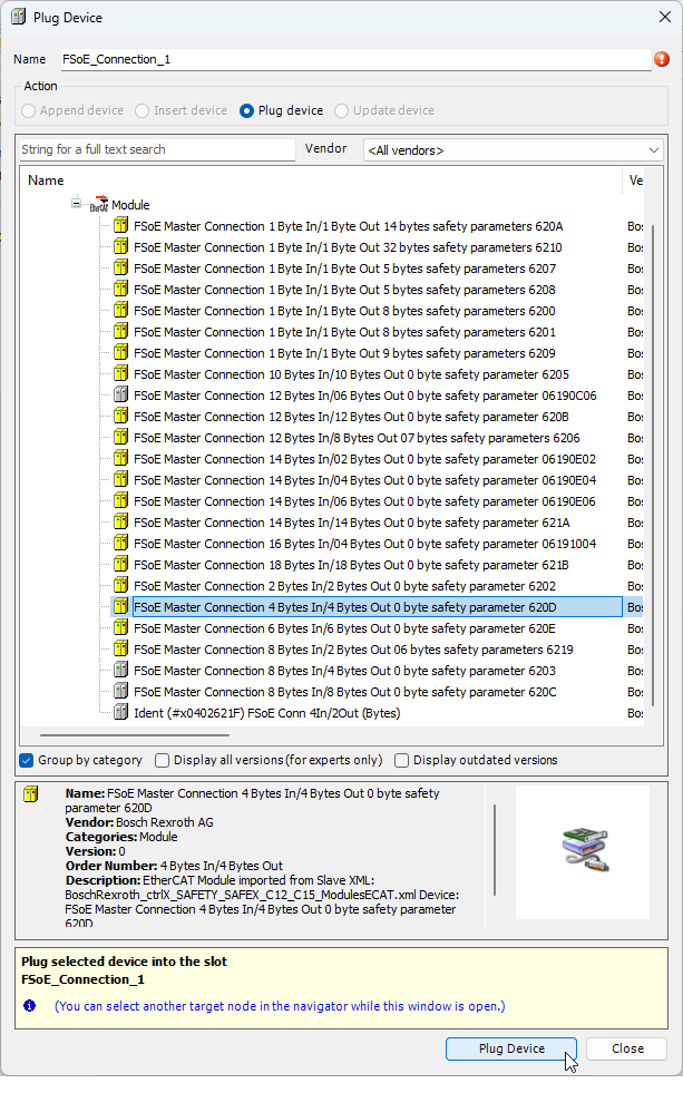
1.2 The SAFEX is successful added to the project and we are ready to setup the FSoE connections. As the ROKIT Motor is the first Safety Device in the EtherCat Bus, we must change the "FSoE_Connection_1" of the SAFEX. Right-click on "FSoE_Connection_1" and hit "Plug Device..."
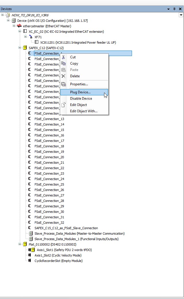
The correct size of the FSoE connection to the Wheel Drive Unit for FSoE with STO is the 4 Bytes In/4 Bytes Out connection. The size will remain the same when adding more safety functions like SS1, SLS, etc. If you add the transmission of the safe velocity, the size changes to 6 Bytes In/6 Bytes Out. In this How to, only the STO via FSoE is configured.
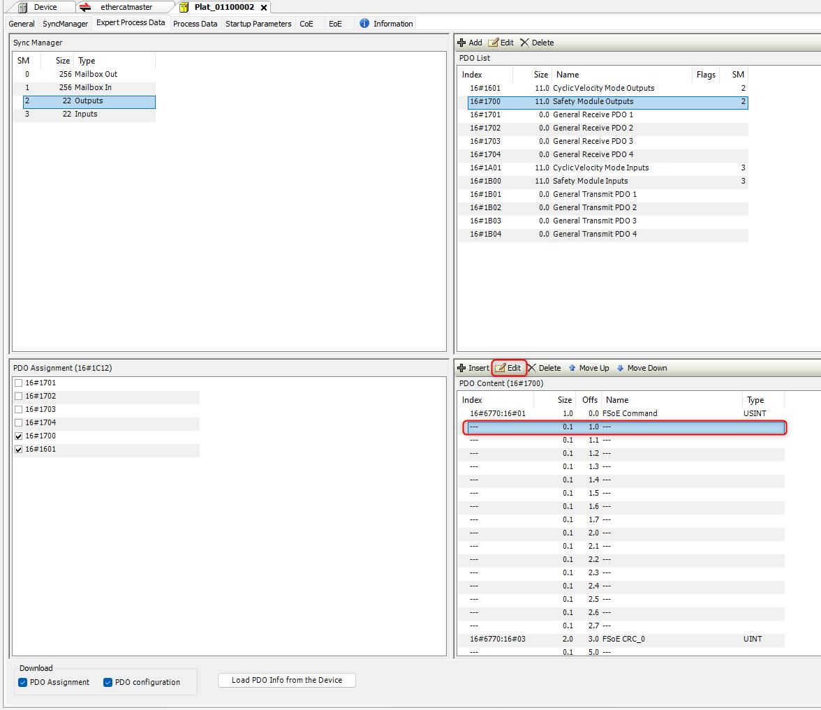
1.3 Double-click on the Platinum Drive and move to the tab “Expert Process Data”, choose the “Safety Module Outputs”, mark the second line and change the value via the "Edit" button.
Frequent mistake: Avoid the handling with "+Insert" since the data length will not match anymore resulting in compile-faults.
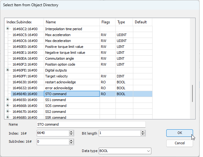
Select the "STO Command 0x6640" and click "OK".
1.4 Choose “Safety Module Inputs,” edit the second entry, and select the "STO Command 0x6640", exactly as you did in 1.3
1.5 Double click on "ethercatmaster" move to the "Slave to slave" tab, and add the communication from source to destination:
From the safety master to the safety device
From the safety device to the safety master
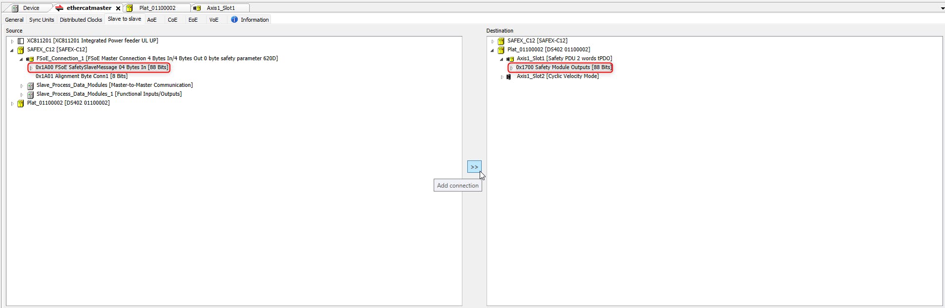
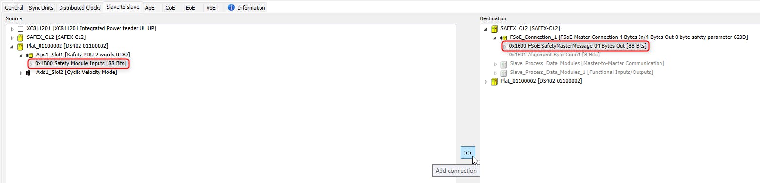

1.6 Download the project to the control.
🚀 You are done with the Settings in ctrlX I/O Engineering.
2. Change the parameters of the ELMO Motion Controller with Elmo Application Studio
2.1 Connect to the Elmo Drive, either via EoE or as a direct connection via USB on the XF06 connection at the Wheel Drive Unit. After connection, move to the Tab "Expert Tuning" and start editing the "Functional Safety" page.
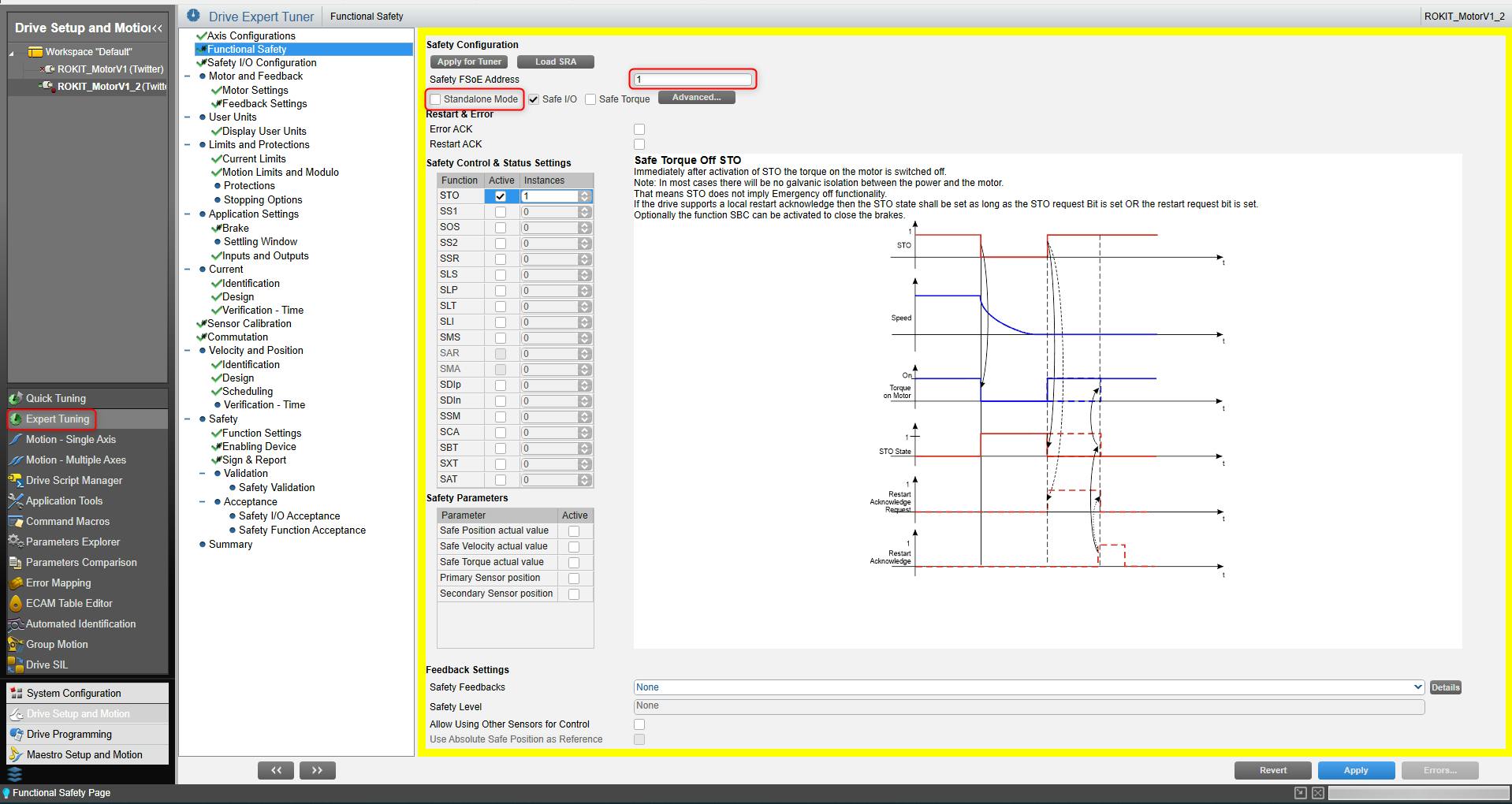
2.2 Edit Functional Safety Settings
By default, the drive is in "Standalone Mode" which means that FSoE is disabled. Disable "Standalone Mode" and assign an unique "Safety FSoE Address" to the device. It must be entered and consistent to the slave properties in ctrlX SAFETY Engineering, described in chapter 3.3.
Enable the STO Function in the "Safety Control & Status Settings" table.
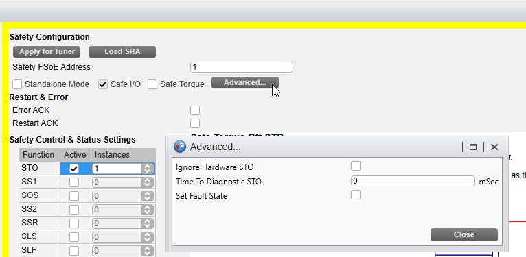
2.3 On the same "Functional Safety" page, click "Advanced...". You can now choose whether the Hardware STO should be ignored or not. If only the FSoE connection is used, it is recommended to ignore the Hardware STO.
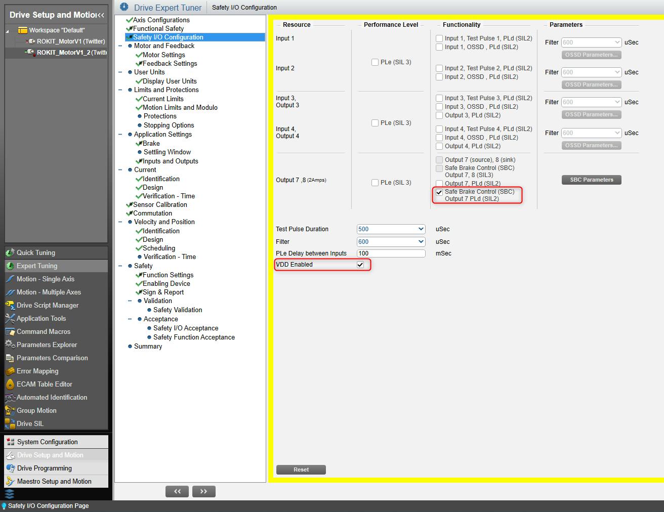
2.4 Move to the "Safety I/O Configuration" page.
Enable "Safe Brake Control" on Output7 with PLd. The standard SBC parameters are suitable.
Enable VDD (required to open the brake)
2.5 Move to the "Sign&Report" page.
Click on "Apply SRA": Now the safety settings are flashed to the drive, and the drive is rebooted.
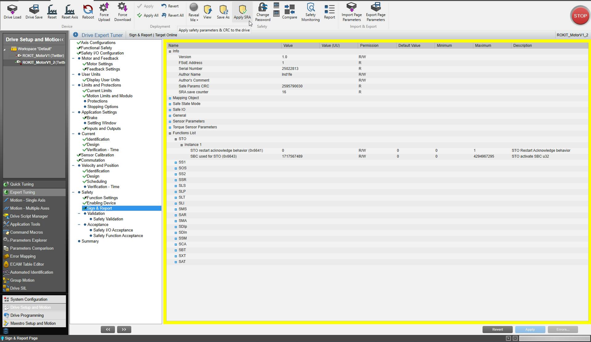
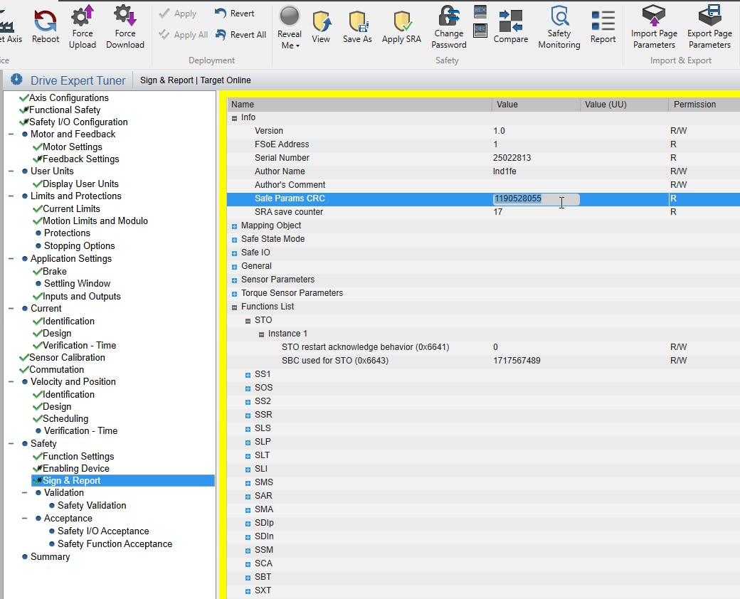
2.6 By saving the safety settings, a new "Safety Params CRC" checksum was generated. This CRC is required for step 3.3 in the ctrlX SAFETY Engineering.
🚀 You are done with the Settings in Elmo Application Studio.
3. Create the Safety Project in ctrlX SAFETY Engineering
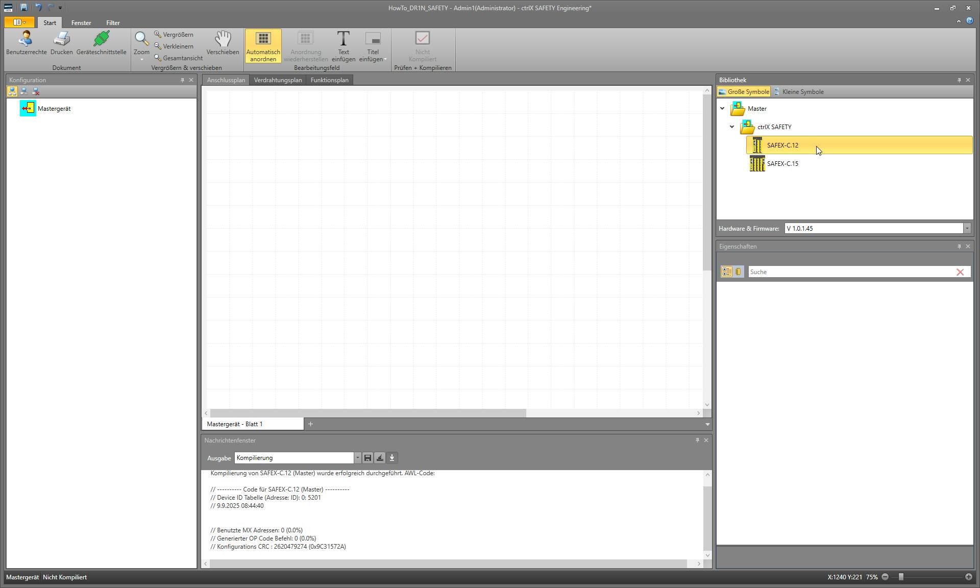
3.1 Open a new safety project and add the ctrlX SAFETY device to your project, depending on your hardware.
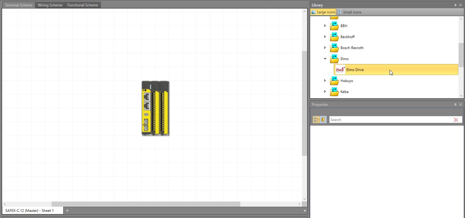
3.2 Add an "Elmo Drive" to the project.
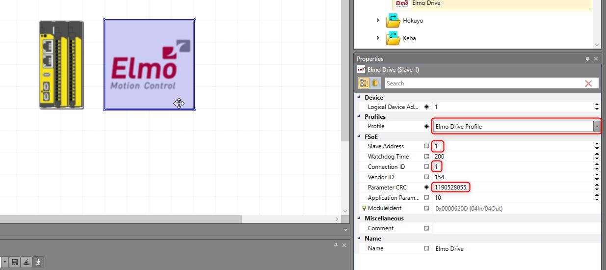
3.3 Edit the properties of the "Elmo Drive", choose the "Elmo Drive Profile", enter the "Slave Address" and the "Parameter CRC" from step 2.6. The "ConnectionID" is another unique ID, that has nothing to do with the "Slave Address". The "ConnectionID" is part of the FSoE telegram that is send to the slave. The "ConnectionID" is only set in the ctrlX SAFETY Engineering - it is transmitted from the master to the slave at the startup.
As an analogy for better understanding, the "FSoE Slave Address" could be your postal address, and the "Connection ID" is the parcel tracking number.
The "Logical Device Address" is assigned automatically to the slave.
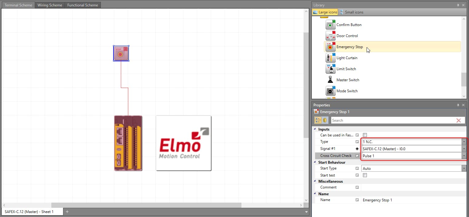
3.4 Add an "Emergency Stop" to the project and edit the properties according to your hardware.
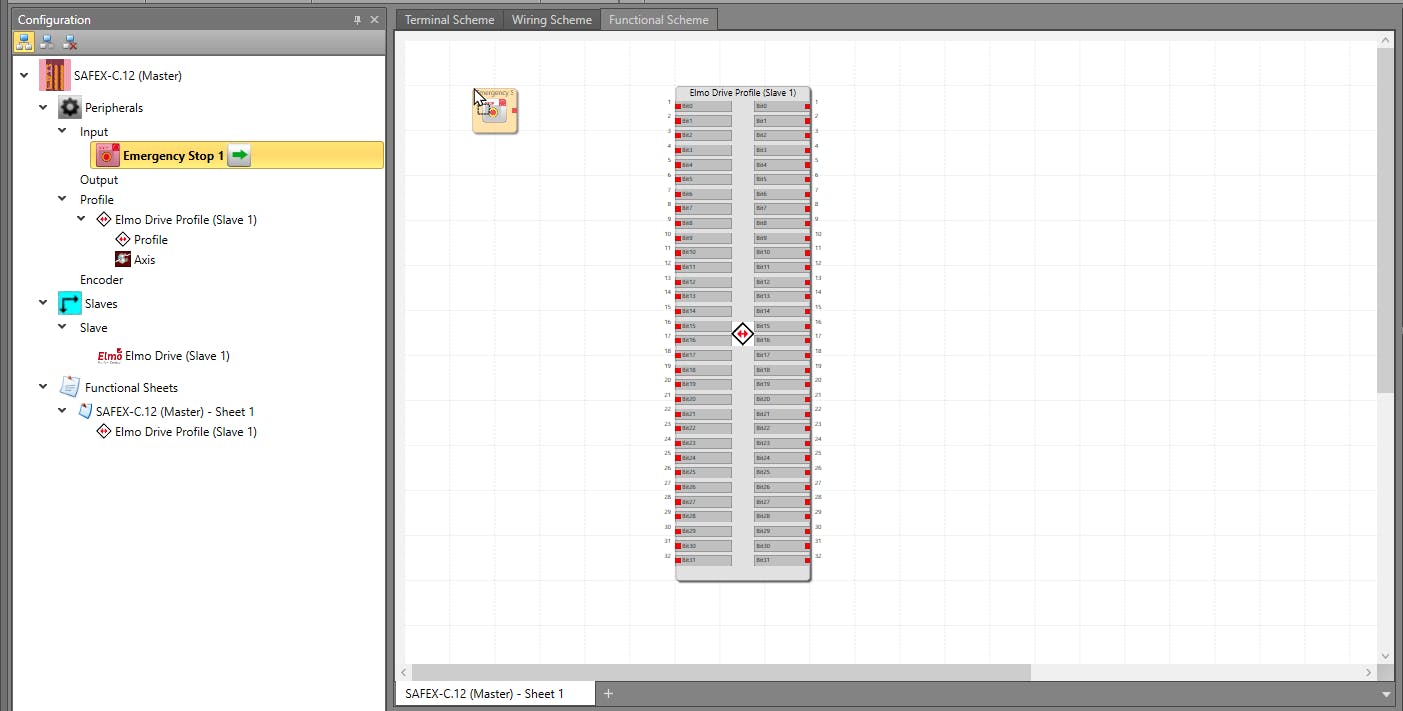
3.5 Move to the "Functional Scheme" tab and add the "Elmo Drive Profile" and the "Emergency Stop" via drag and drop.
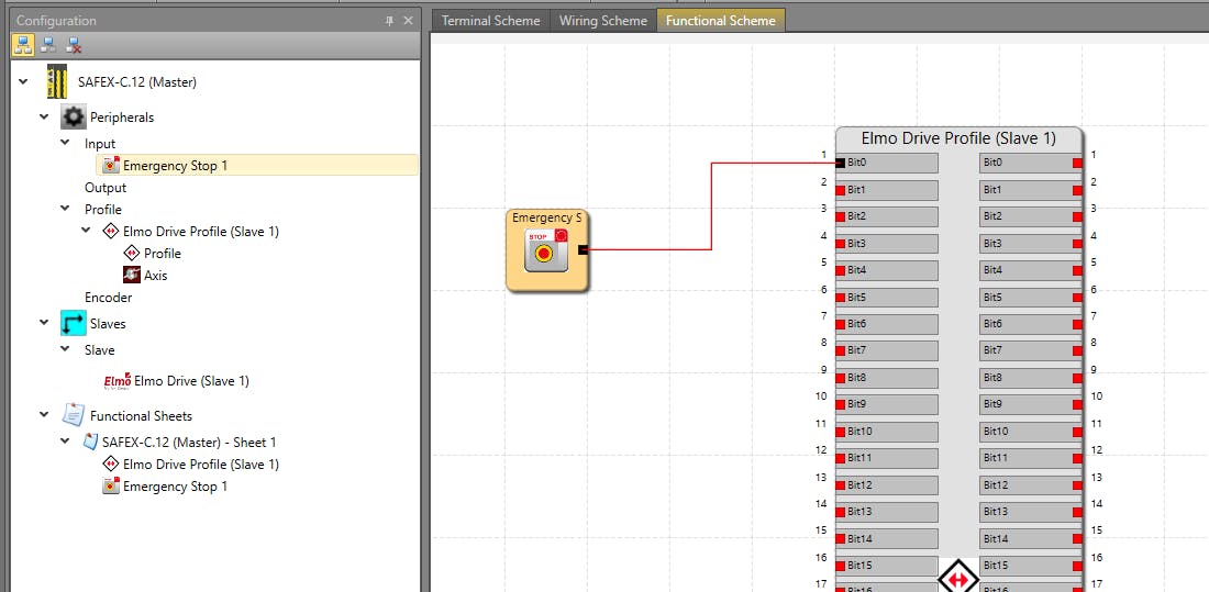
3.6 Connect the "Emergency Stop" to the first connection, "Bit0", of the "Elmo Drive Profile".
3.7 Move to the "Wiring Scheme" tab and make sure your hardware matches to the wiring scheme displayed.
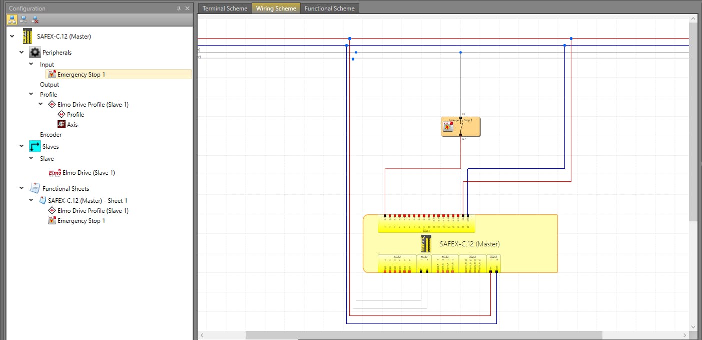
3.8 Send the configuration to the device
Open the "Device Interface".
Click "Connect" and enter the serial number.
Click "Secure" and enter the password.
Click "Send Configuration".
3.9 The Status of the SAFEX device should change to "Run", the LED on the device will blink green.
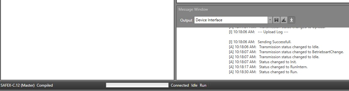
3.9.1 Troubleshooting
If the device does not change to "Run", try recycling the EtherCat bus (OP -> init -> OP) and resetting the SAFEX Device by pressing the reset button on it.
If the Status is "Run-intern", there is a problem with the FSoE settings.
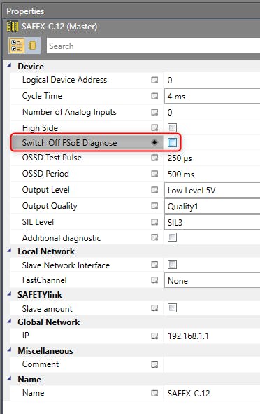
In the "Properties" of the SAFEX Device, you can enable the "FSoE Diagnose" to get a more detailed error message.
Properties of the SAFEX device in ctrlX SAFETY Engineering. Enable "FSoE Diagnose" for more detailed error messages.
🚀 You have now integrated the Wheel Drive Unit into the ctrlX Solution with ctrlX SAFETY and communication via FSoE and can proceed to develop your own application 🚀