Overview
OverviewPrerequisitesStep 1: EtherCAT Topology (create the topology in ctrlX IO Engineering)Step 2: PLC Project (create / edit the PLC Project)Step 3: Test the PLC ProjectStep 3.1: ExampleProgram_Generic: (example program for generic M-Bus device use)Step 3.2: ExampleProgram_PadPulsM1C: (example program (device - specific) for reading and resetting/writing)Step 3.2.1: Read Counter Data (read M-Bus device data)Step 3.2.2: Reset Counter Data (reset and read with preset values)Telegram Structures (Manufacturer-Specific)ConclusionLinks to info & sources on the topic
Prerequisites
ctrlX PLC Engineering ≥ 3.6
ctrlX IO Engineering ≥ 3.6
ctrlX WORKS version ≥ 3.6 or ≥ 4 (required to use the integrate Help of "Ask IXI")
ctrlX CORE X3 controller
ctrlX I/O modules: Bus Coupler (XB-EC-12), DI16 (XI110116), DO16 (XI211116), M -Bus Master (XI531001)
Relay PadPuls M1C pulse counter device
ctrlX CORE X3, I/O DI 16 | DO 16 | M-Bus Master, Relay PadPulsM1C CXA_MBus library available in ctrlX PLC Engineering
DO16 output wired to the Relay PadPuls M1C pulse input for test signal generation
Network connection the between engineering PC and ctrlX CORE (IP 192.168.1.1)
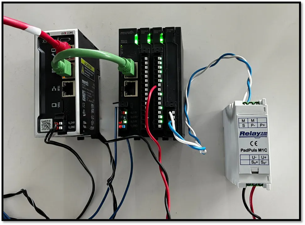
Step 1: EtherCAT Topology (create the topology in ctrlX IO Engineering)
The EtherCAT topology can be created either by scanning the physically connected devices or by adding each participant manually. In this guide, we add the M-Bus module manually to an existing topology.
⚠️ Notice!
By default, a new M-Bus device has the factory-preset primary address 16#00. In this example, we will change/set the address of the Relay PadPuls M1C to 16#08.
Open ctrlX IO Engineering and create a new or open your existing project.
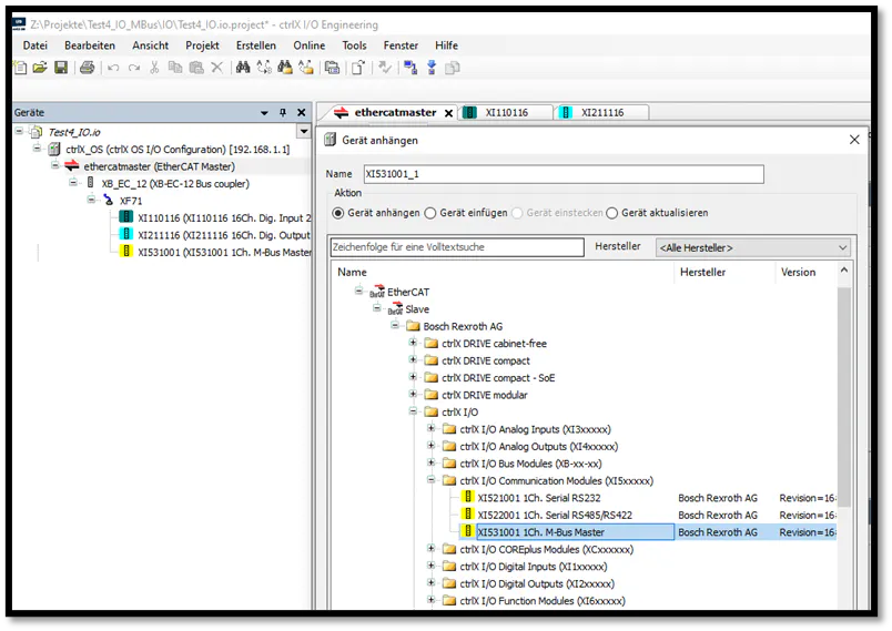
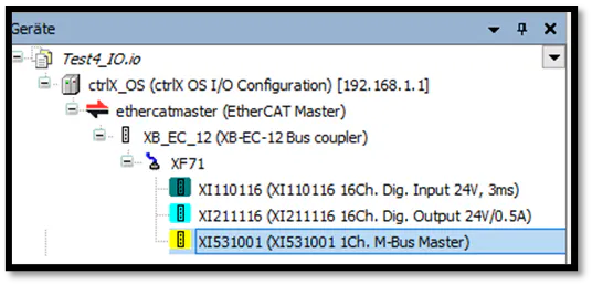
Add the XI531001 1-channel M-Bus Master module to the existing topology under the XB-EC-12 Bus Coupler (alongside the XI110116 DI16 and XI211116 DO16 modules).
After creating the topology, the IO image can be loaded into the PLC.
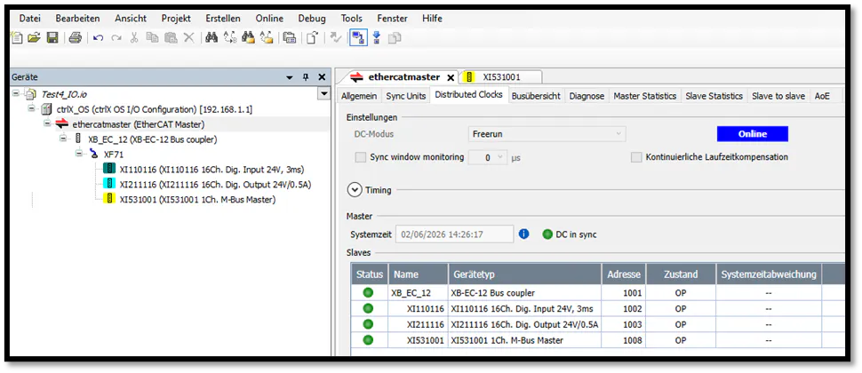
Use the ctrlX IO Engineering online view to verify the error-free module state (OP) for all EtherCAT slaves.
ctrlX IO Engineering device dialog showing XI531001 1Ch. M-Bus Master selected under ctrlX I/O Communication Modules
Step 2: PLC Project (create / edit the PLC Project)
Open ctrlX PLC Engineering and create a new or open your existing PLC project. First, test the online connection to the controller.
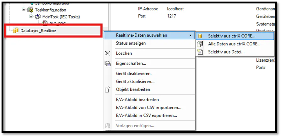
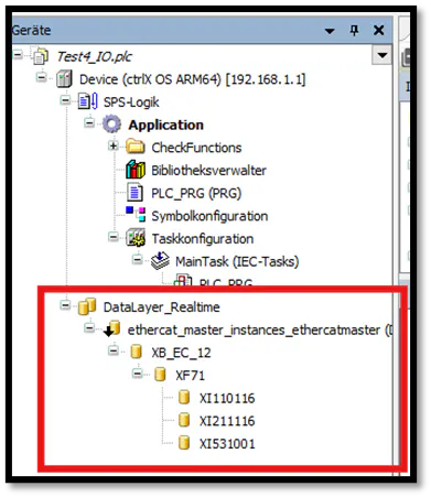
Once connected, right-click on the DataLayer Realtime node and select "Select Realtime Data" → "Selectively from ctrlX CORE..." to import all reachable EtherCAT master participants into the PLC project.
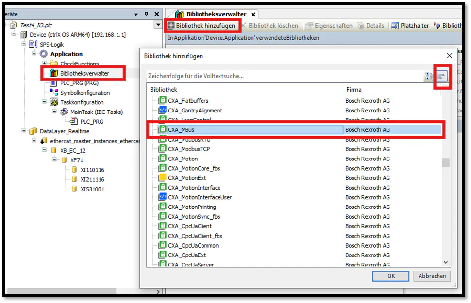
After importing the EtherCAT master instances under the DataLayer node, open the Library Manager and add the CXA_MBus library. We will use the integrated "example" programs provided by this library.
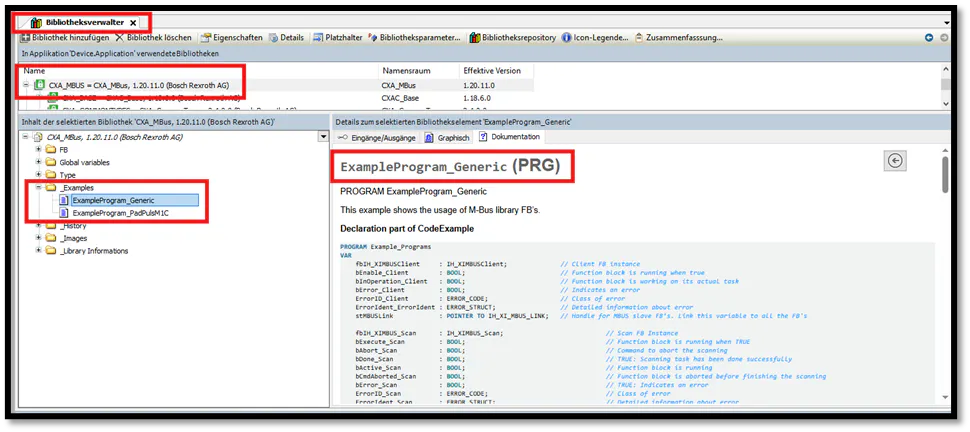
Once added, the library's example programs and their functional descriptions will be visible. You can copy the code directly from the Library Manager and paste it into your own Program Organization Units (POUs).
Create a new POU of type Program using Structured Text (ST). To keep things clear, use a name similar to the library example. Paste the copied code into this new POU.
The example program code references predefined peripheral addresses for the XI531001 M-Bus module (e.g., %IB295, %QB142). You must either map these exact addresses in your I/O configuration or update the address variables in your POU declaration to match your actual I/O image.
Right-click context menu on DataLayer_Realtime node showing option to select realtime data selectively from ctrlX CORE
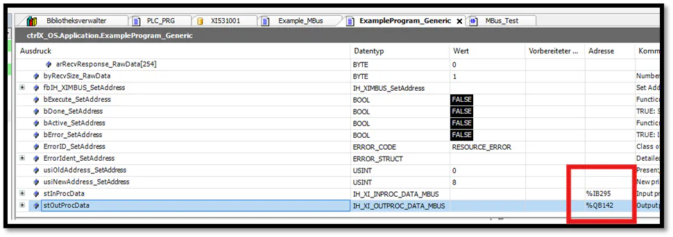
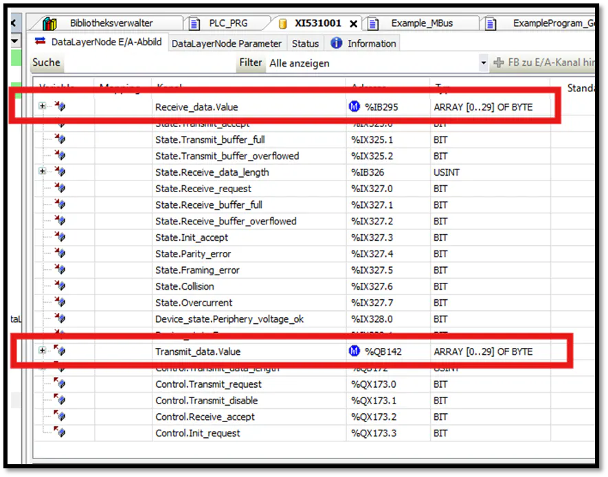
Step 3: Test the PLC Project
In this How-To, a generated clock signal is used, coming from a digital output and wired to the Relay pulse input. This is implemented in the PLC_PRG program.
After implementing all programs and their calls, use F11(Compile) to check for errors and Alt+F8 (Login/Download) to switch to the online state to continue testing or load new code.
Start the PLC after downloading and perform F5 (Play button to run the PLC)!
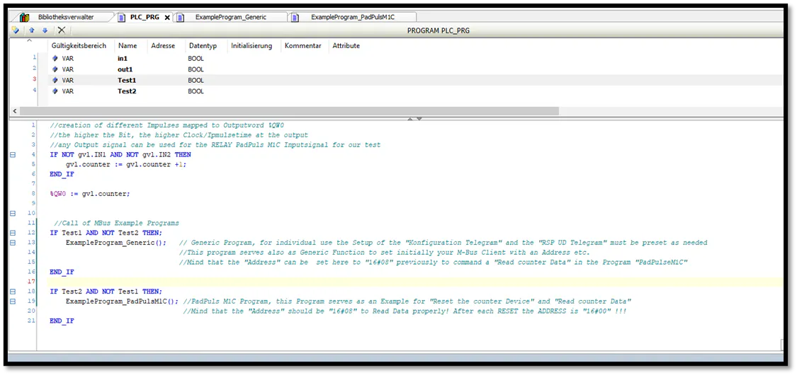
Step 3.1: ExampleProgram_Generic: (example program for generic M-Bus device use)
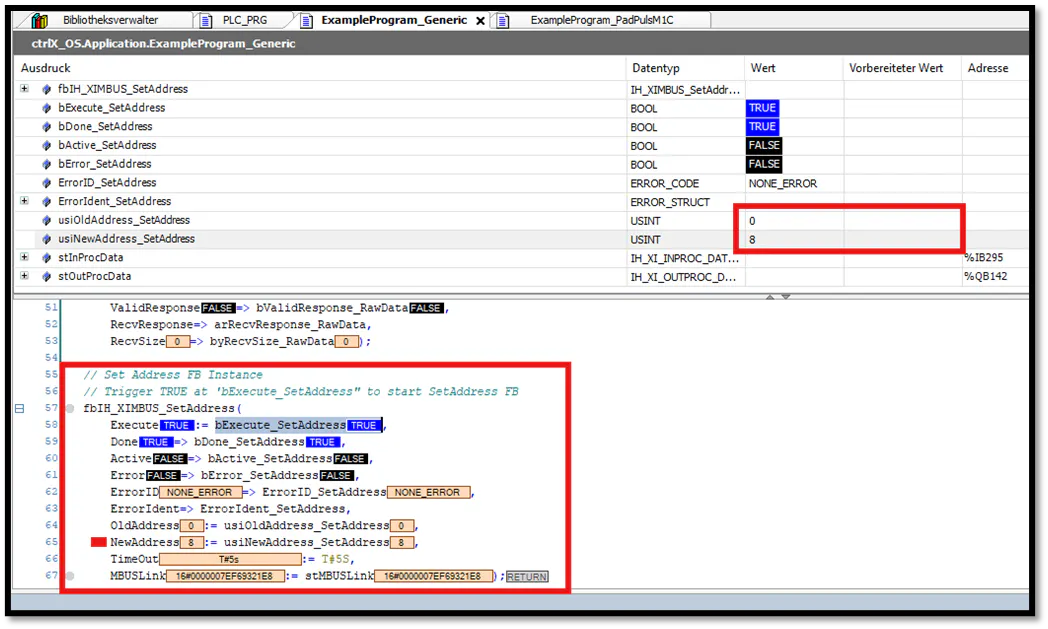
In PLC_PRG, call the ExampleProgram_Generic first to configure the M-Bus device's address to 16#08.
Enable the connection to the client by setting bEnable_Client to TRUE within the fbIH_XIMBUSClient block.
You can execute a scan (fbIH_XIMBUS_Scan) to verify that the Relay PadPuls M1C is recognized on the bus.
To write the target address 16#08 to the device, assign this value to the variable usiNewAddress_SetAddress in fbIH_XIMBUS_SetAddress, and trigger the write command by setting bExecute_SetAddress to TRUE.
Once successful, bDone_SetAddress will turn TRUE, and the new address is active. Reset the trigger (bExecute_***) and enable (bEnable_***) variables to complete the sequence.
The device is now assigned to address 16#08 and is ready for device specific data queries.
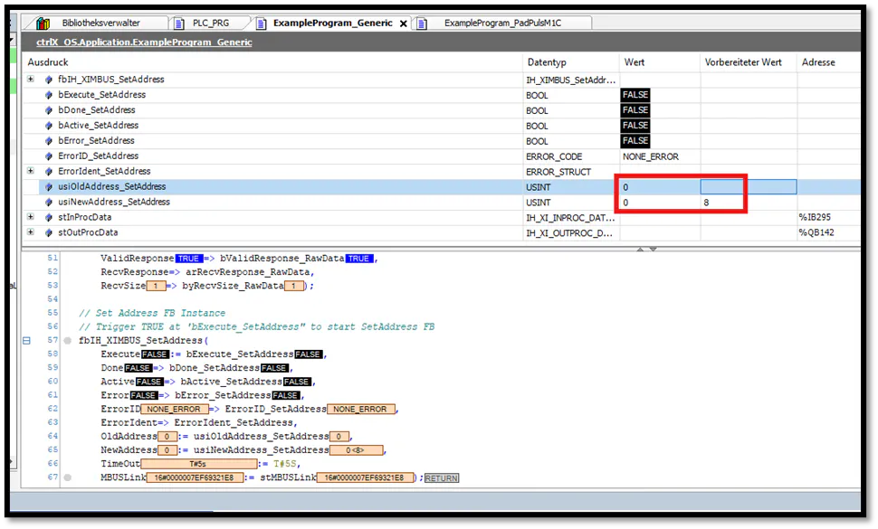
Step 3.2: ExampleProgram_PadPulsM1C: (example program (device - specific) for reading and resetting/writing)
We will now switch to the device-specific program. You can temporarily deactivate the generic program call in PLC_PRG.
In ExampleProgram_PadPulsM1C, the enable variables (bEnable_***) for fbIH_XIMBUSClient and fbIH_XIMBUS_RawData are pre-set to TRUE. Because our digital output has been sending pulses to the Relay PadPuls M1C while the PLC was running, the hardware counter has already accumulated pulses.
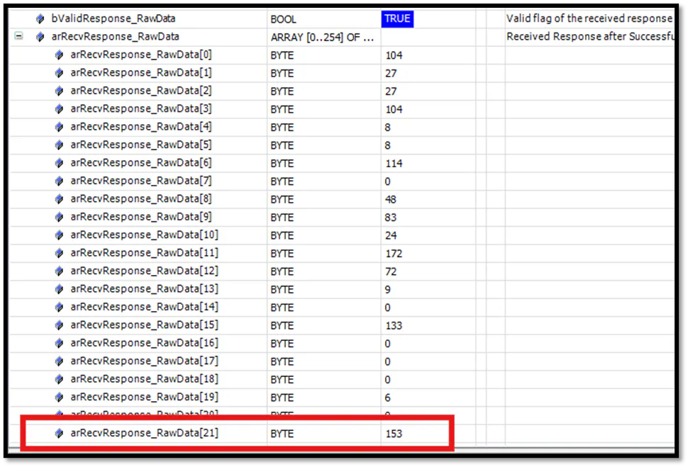
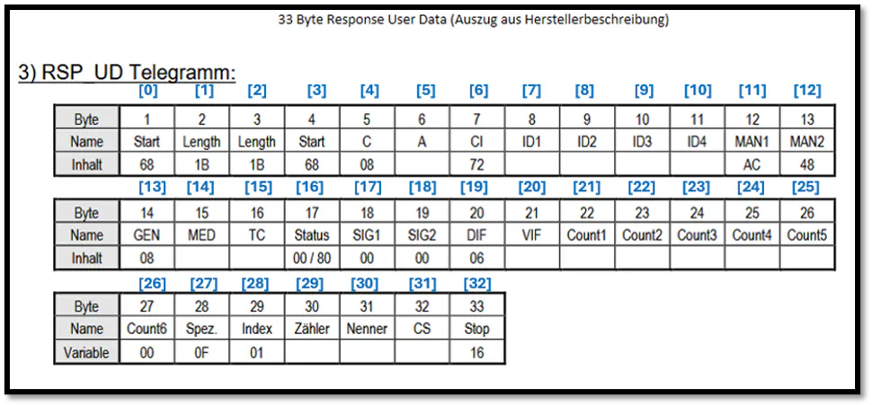
We will read this counter value from the raw data array under index [21] (arRecvResponse_RawData[21]). An explanation of this telegram structure is provided at the end of this document.
Step 3.2.1: Read Counter Data (read M-Bus device data)
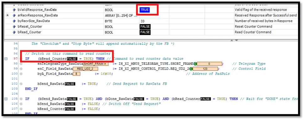
Trigger the read sequence by setting bRead_Counter to TRUE. The variable will automatically reset to FALSE, and bValidResponse_RawData will turn TRUE to indicate a successful read.
The controller receives a 33-byte data payload, which corresponds to the RSP_UD telegram (refer to the Relay PadPuls M1C operating manual).
The counter value (Count1) is located at index [21] of the received array.
💡 Why Index 21?
According to the standard RSP_UD telegram structure, the counter starts at byte 22. However, since the PLC data structure uses a zero-based array ([0..254]), Byte 22 corresponds to index [21].
Step 3.2.2: Reset Counter Data (reset and read with preset values)
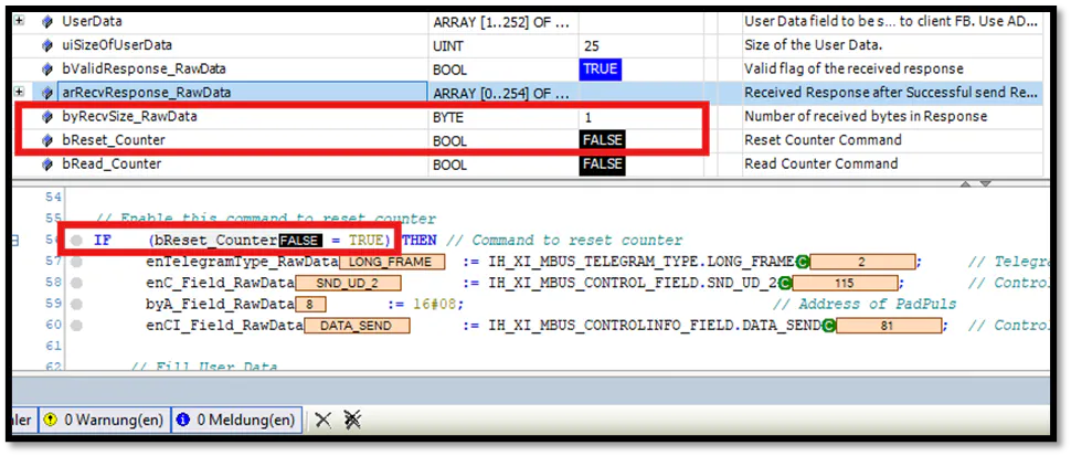
Using the variable bReset_Counter, you can either reset the physical device to factory defaults or write custom preset values (configured in lines 62–67 of ExampleProgram_PadPulsM1C) into the data structure. This process transmits a configuration telegram (SND_UD) to the device.
⚠️ Important Note on Resetting:
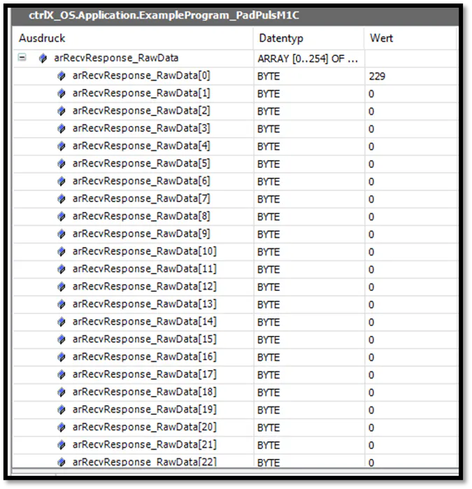
Performing a hardware RESET changes the device's primary address back to 16#00. To read the device again afterwards, you must first switch back to the generic program and re-assign the address to 16#08.After a successful reset, the received data length will drop from 33 bytes to 1 byte (with arRecvResponse_RawData[0] = 229 / 16#E5 representing the single-character acknowledgment).
Writing Preset Values during Reset
Instead of simply clearing the counter, you can use the Reset command to write preset values (e.g., pre-loading a specific counter state).
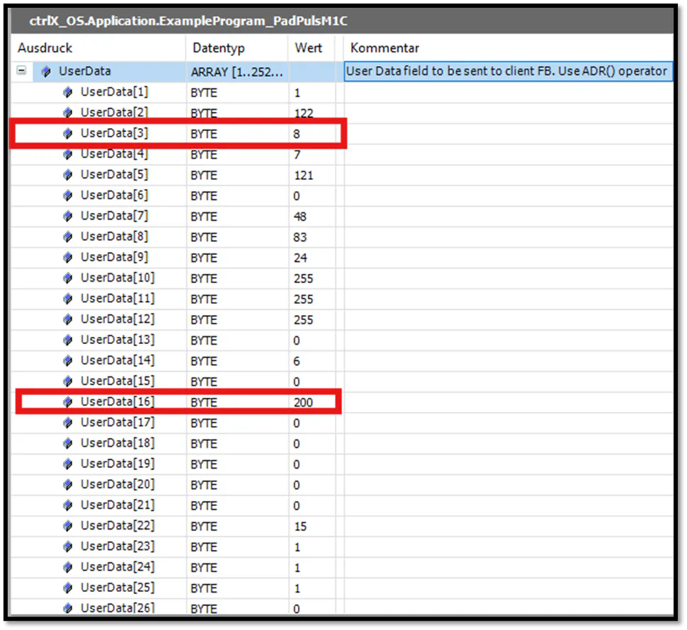
To do this, we configure the configuration telegram to write the primary address 8 to Byte 10 (UserData[3] / "Padr") and initialize the counter Count1 on Byte 23 (UserData[16]) with a start value of 200.
🔧 Test Tip:
Temporarily disconnect the physical pulse input on the Relay PadPuls M1C before sending this command. This prevents the counter from immediately incrementing and ensures you can verify the exact preset value of 200.To ensure the controller can talk to the device during this command (since a previous reset might have reverted it to address 0), ensure that the peripheral address variable byA_Field_RawData is temporarily set to 0 that the device can be found.
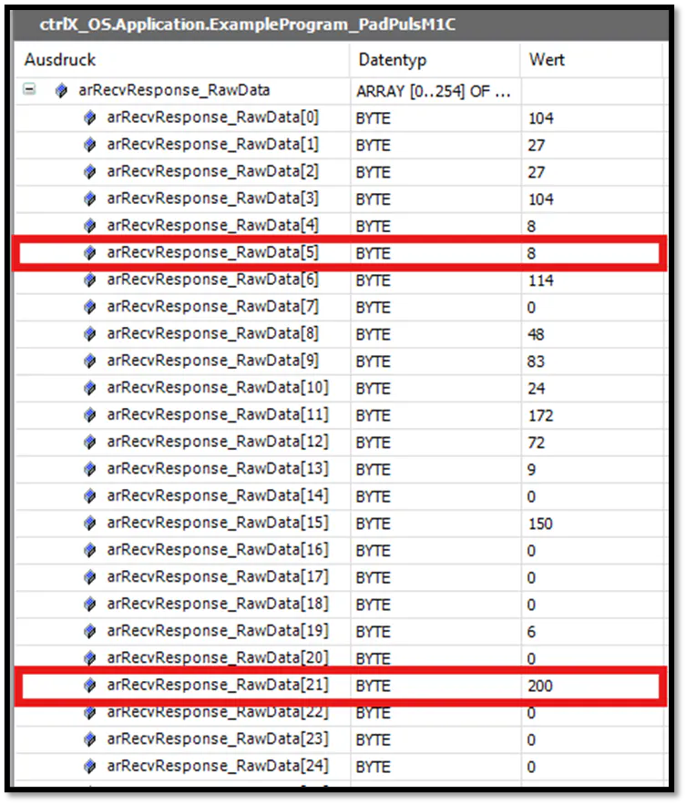
Once you execute bReset_Counter followed by bRead_Counter, the array arRecResponse_RawData will update. You can verify that the counter value at [21] (Count1) is now initialized to 200 and the primary address at [5] (A) is set to 8.
Telegram Structures (Manufacturer-Specific)
The following section describes the structure of the telegrams used:
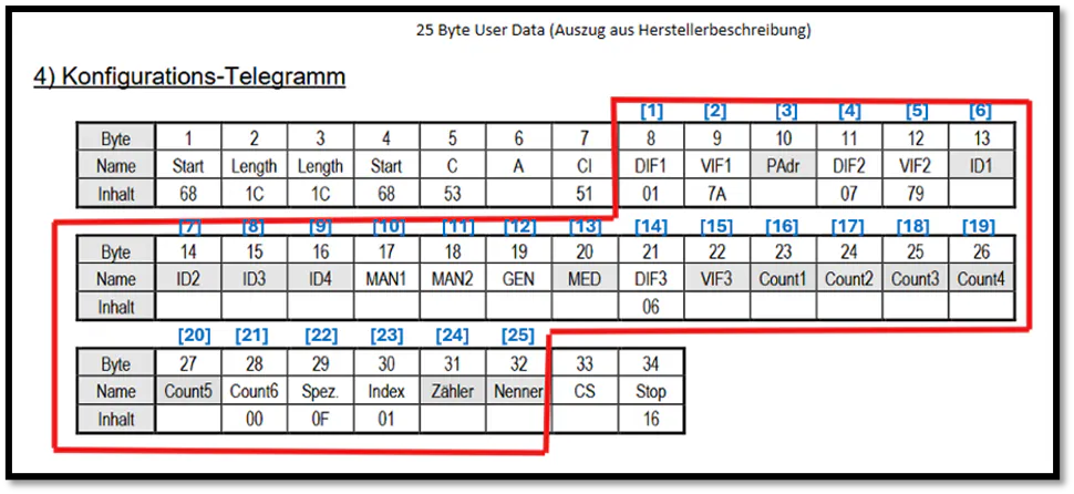
Composition of the UD configuration telegram (UserData)
Configuration telegram overview. Edit for 25 bytes (UD: 8 - 32). Composition of the RSP_UD telegram (arRecvResponse_RawData)
Response User Data telegram overview. 33 bytes data response.
Conclusion
By combining the ctrlX I/O XI531001 M-Bus Master module with the CXA_MBus library in ctrlX PLC Engineering, users can easily read, configure, and reset M-Bus slaves such us the Relay PadPuls M1C pulse counter directly from a ctrlX CORE PLC.
Links to info & sources on the topic
M-Bus SDK library for ctrlX I/O:
https://community.boschrexroth.com/ctrlx-os-store-apps-oc2pqqwn/post/m-bus-library-and-sdk-library-for-ctrlx-i-o-sPR7VGXyUqqsfcpGeneral ctrlX I/O Application Description:
https://www.boschrexroth.com/media/541b95eb-d3b8-4259-80b9-82425c4369fbGeneral M-BUS Documentation: https://m-bus.com/documentation
ctrlX I/O M-Bus Master Communication Module XI531001 Datasheet:
https://www.boschrexroth.com/media/5067eab4-f8fe-413a-80dd-5d0681f4bdb5RELAY PadPulsM1C: