Introduction
In this article I will show you a newly developed dashboard for controlling an AGV (Automated Guided Vehicle) equipped with ROKIT (The Robotics Kit by Bosch Rexroth) components, realizing functions such as single instruction control and template trajectory cruising.
The Dashboard can be directly imported into the Core on the AGV, or it can be used in the virtual Core on the PC, but in this case, you need additional simulation software because you are controlling a virtual AGV in the simulator.
For more information about ROKIT, please go here.
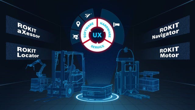
General
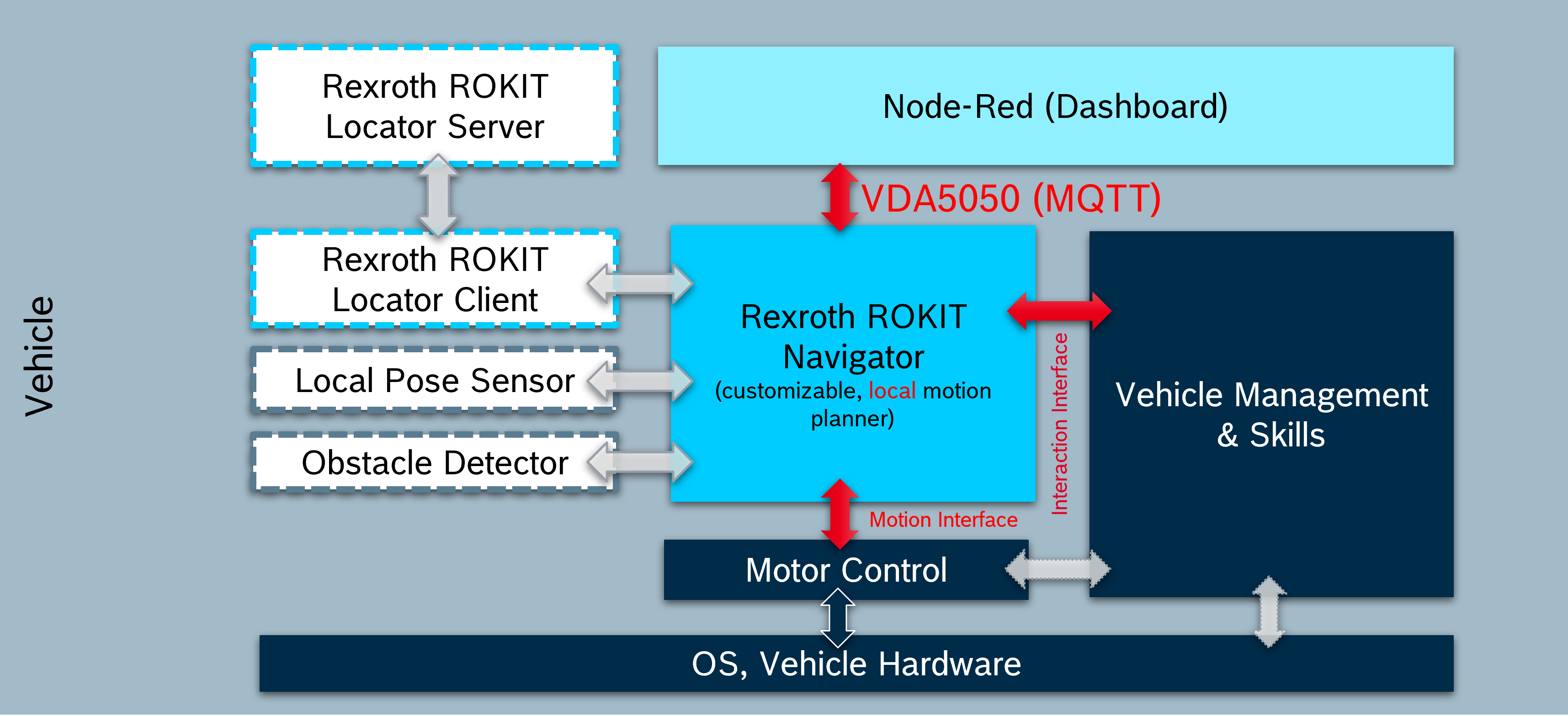
The software provides an operation panel that constructs VDA 5050 commands based on the user's parameter settings and sends them to Navigator via MQTT. Navigator then converts them into lower-level commands to control motors and other actuators to achieve motion.
Among them, the MQTT broker can be installed on the Core, or the broker node in Node-RED can be used.
More information about MQTT connection can be found here.
More information on VDA 5050 standard directives can be found here.
Below is the topology diagram of the AGV system.
Graphical interface
The dashboard is divided into 6 pages: Home, Manual, Automatic, Interaction, Settings, Route. The right and bottom sidebars on each page are fixed and used for common input and output functions. The following is a description of each page. The page Interaction is still work in progress and will therefore not be discussed here. Note that orders containing custom actions are validated against the action list defined on this page.
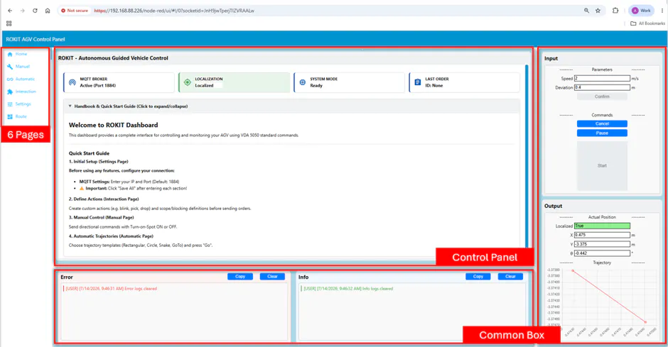
Home: The homepage can display basic AGV information and contain all the relevant information in one view (see picture before). Depending on the status of the simulation, it might also display that the localization is still unknown in red. The Localization tile mirrors the localization flag from the VDA 5050 state topic: it turns green as soon as state messages report a localized vehicle. When a different state topic is applied in the settings, the status is reset to red until data from the new topic proves localization again.
Manual: This page provides a single command operation panel. Different motion modes can be selected according to the different hardware structures of AGV, such as TOS (Turn on Spot). Note: Please check the parameter settings carefully before clicking the arrow buttons. Please check the comment box for the meaning of each parameter.
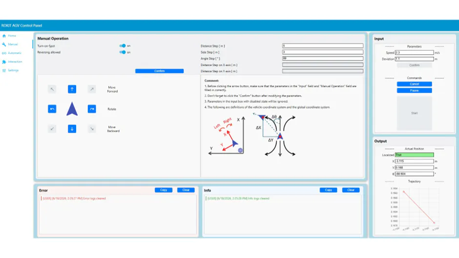
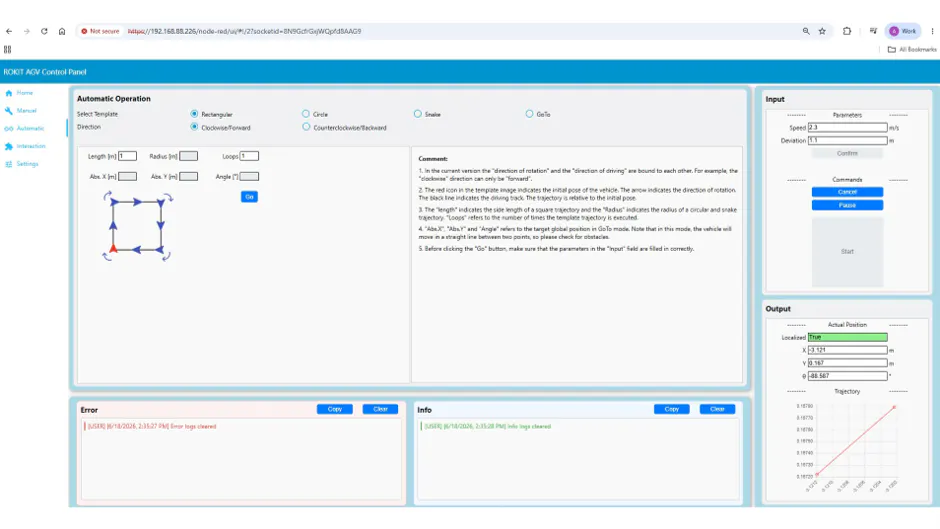
Automatic: This page provides a variety of automatic driving templates, and each trajectory can also select a different driving direction. Please check the comment box for the meaning of each parameter.
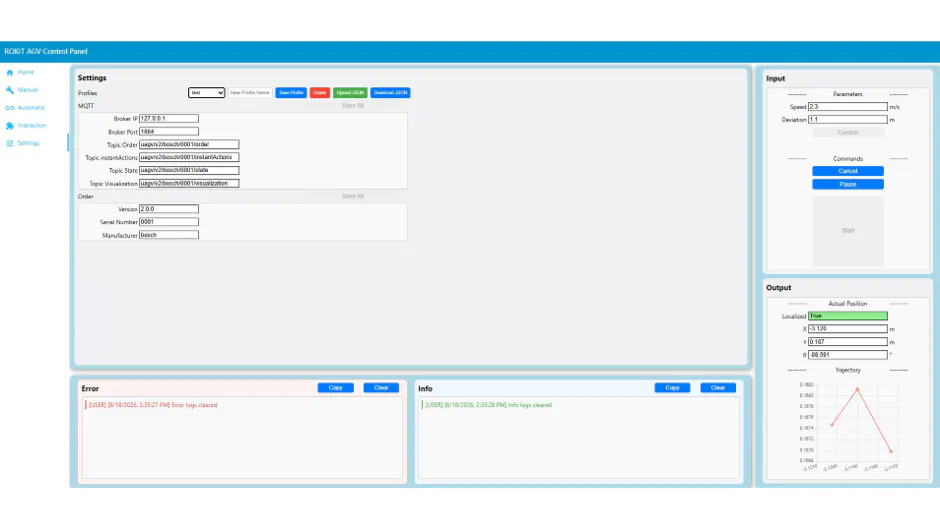
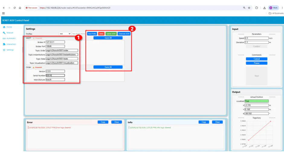
Settings: This page is used for some general settings. Currently, there are settings for the MQTT connection and VDA 5050 commands. Set up and save the content on this page before you start using the dashboard.
Settings are stored in named profiles and can be switched via the dropdown; selecting a profile applies it immediately. Individual field changes only take effect after clicking “Save All” of the respective section. A pulsing “Unsaved” badge indicates pending changes. Profiles can also be exported and imported as JSON. The applied MQTT settings are additionally persisted on the Core (rokit/last_applied_mqtt.json) and restored automatically after every Node-RED restart or deploy, including the MQTT subscription, so the initial setup is only required once.
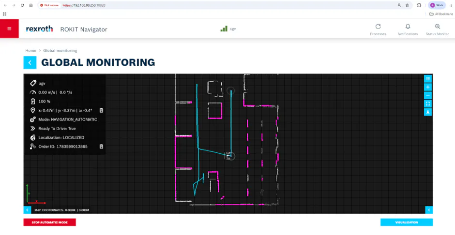
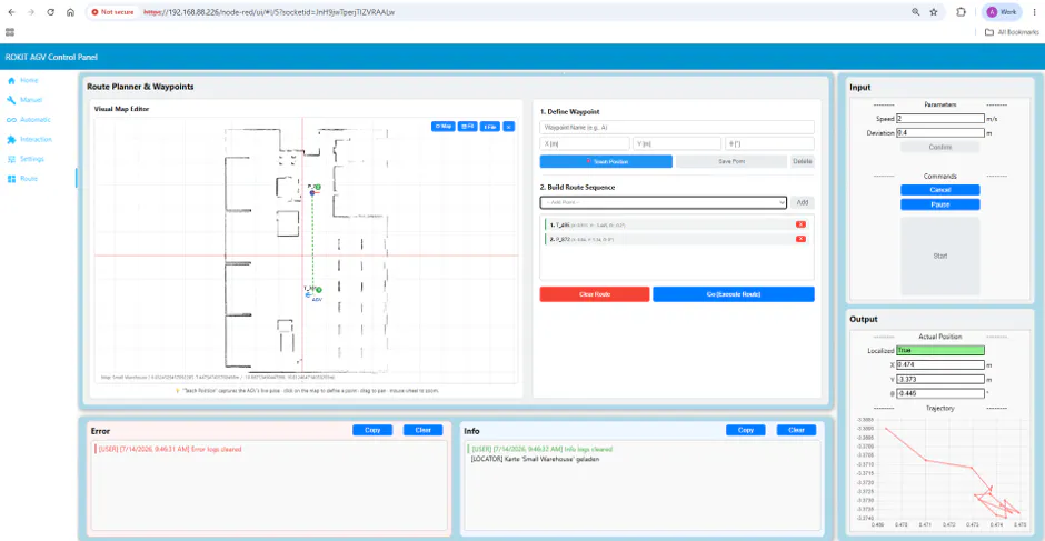
Route: Here you can define single points on the map to build a route. Then the robot can follow this route, either directly on the map or via the “Teach Position” Button. The saved points must be selected in sequence on the right side and are then displayed on the map as a green line. The red line indicates the angle alignment of each point and the blue arrow shows where the robot is currently located.
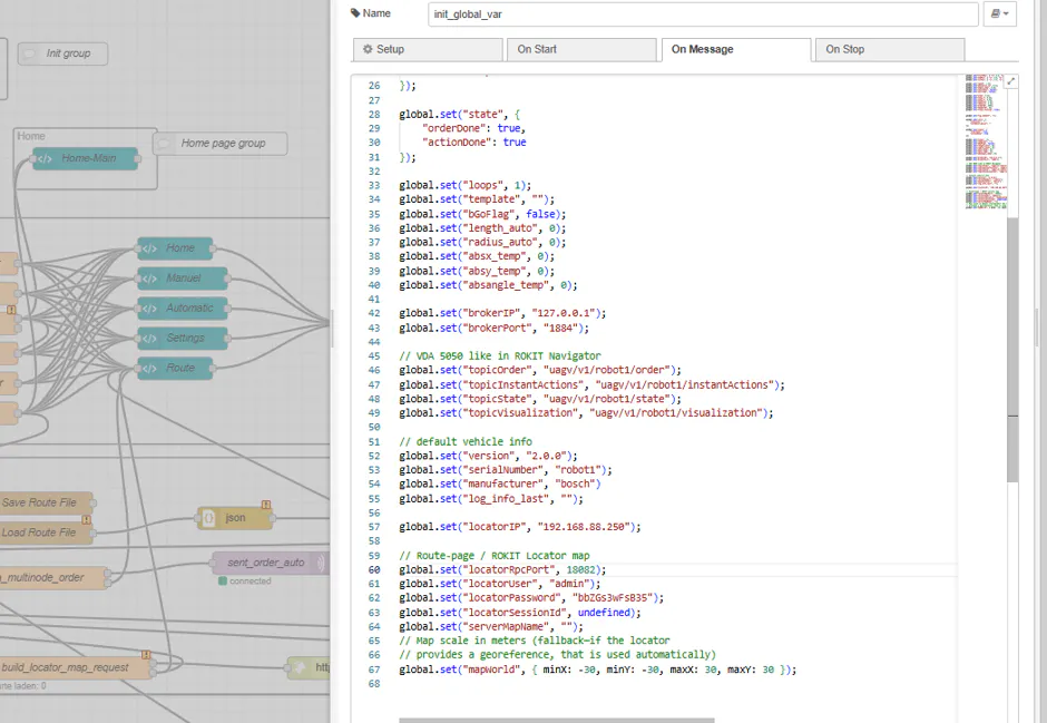
The map is loaded from the ROKIT Locator Server via JSON-RPC (port 18082 on ctrlX OS installations). The connection parameters (locatorIP, locatorRpcPort, locatorUser, locatorPassword) and the map name must be adjusted once in the init_global_var function node for each installation. If the Locator replies with responseCode 11, check the session and the map name. An example of this is shown here
Changeable settings
The “Go” button starts the AGV and only works if it is localized.
Flows
The dash is written based on Node-Red's flow programming combined with HTML, JavaScript and CSS. Here I introduce the overall framework and logic behind the flow.
CSS: All styles are written in the template node. These CSS codes are divided into different groups by element. For example, the button node contains all the styles related to the button, such as the color and size of the button.

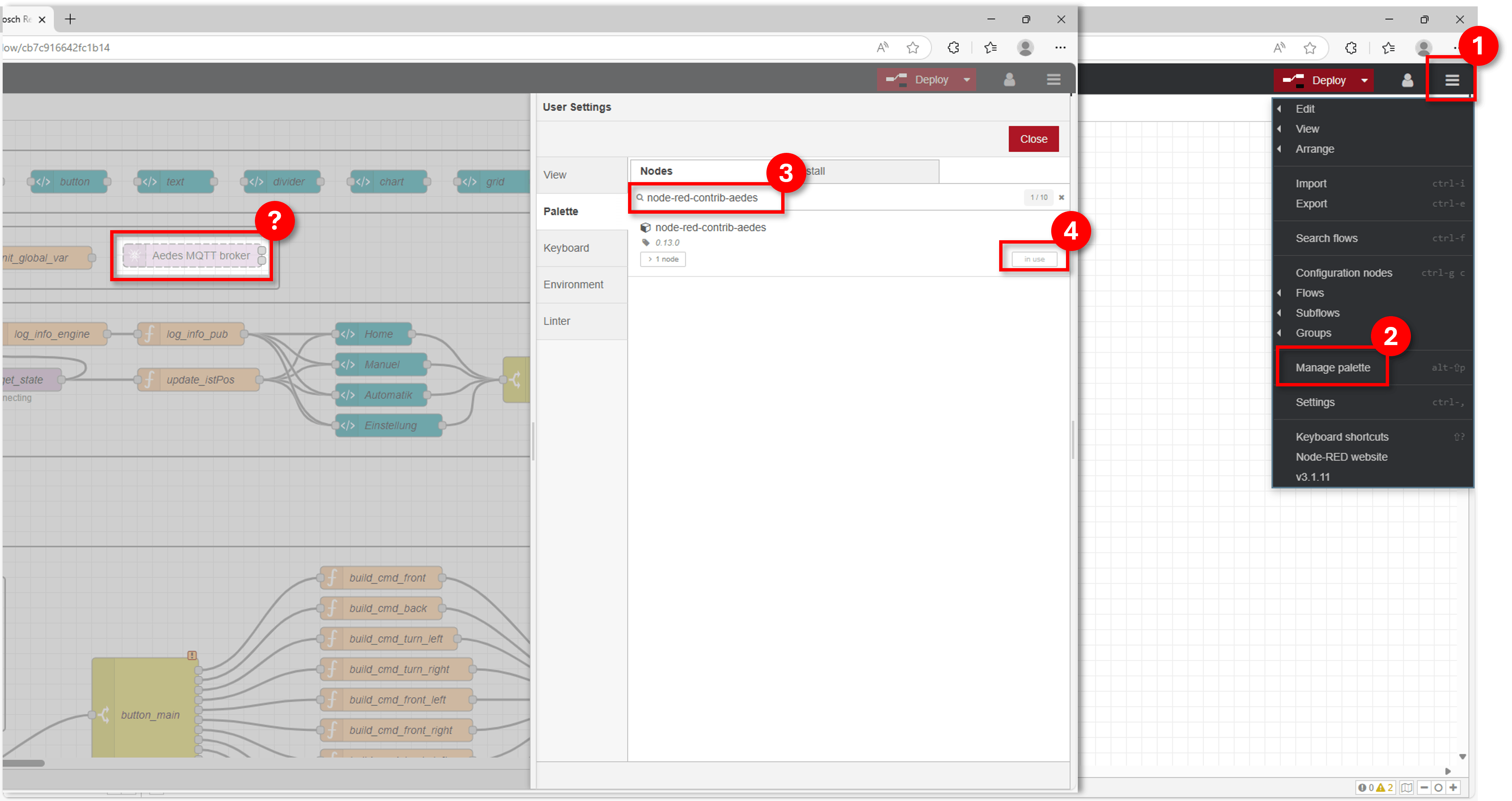
Init: : All global variables will be initialized here. Note that this group also contains an MQTT broker node (1). If you want to use the MQTT Broker node in Node-RED, please search for “node-red-contrib-aedes” in the “Manage Palette” and download it. Otherwise, just delete this node.

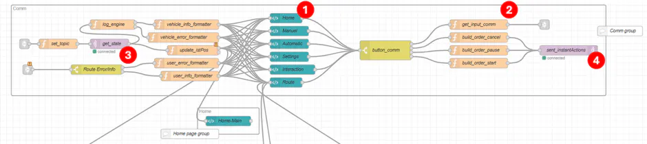
Comm: This group contains the common areas of each page, namely the right and bottom sidebars of the page. The template node (1) contains the HTML code of the graphical interface. The function nodes (2) named build are used to construct the VDA command. There is also an MQTT receiving node (3) and a sending node. The receiving node receives status information from Navigator, such as the AGV's absolute position and speed. The sending node (4) is used to send commands to Navigator. The outgoing paths are connected to the Route panel, which will be discussed later.
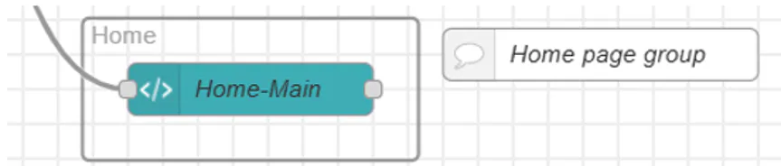
Home: The page content can be customized as needed.
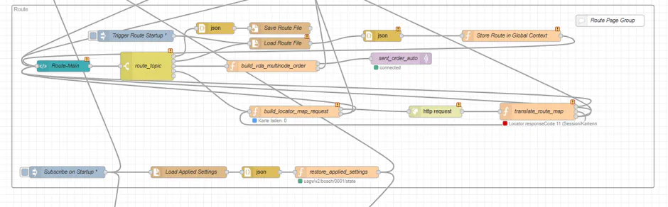
Route: This group contains the map editor and the route execution logic. The template node Route-Main renders the visual map editor. The map is requested from the ROKIT Locator Server via JSON-RPC (build_locator_map_request → http request → translate_route_map) and drawn in the browser together with the live AGV position. Defined waypoints are stored on the Core as a JSON file (Save/Load Route File) and reloaded on startup, analogous to the settings presets. When "Go (Execute Route)" is pressed, build_vda_multinode_order constructs a single VDA 5050 order containing all selected waypoints as nodes and edges and publishes it via the MQTT out node. The order is only sent if the AGV reports a localized position; otherwise, an error is written to the Error box. The "Teach Position" button captures the current AGV pose as a new waypoint.
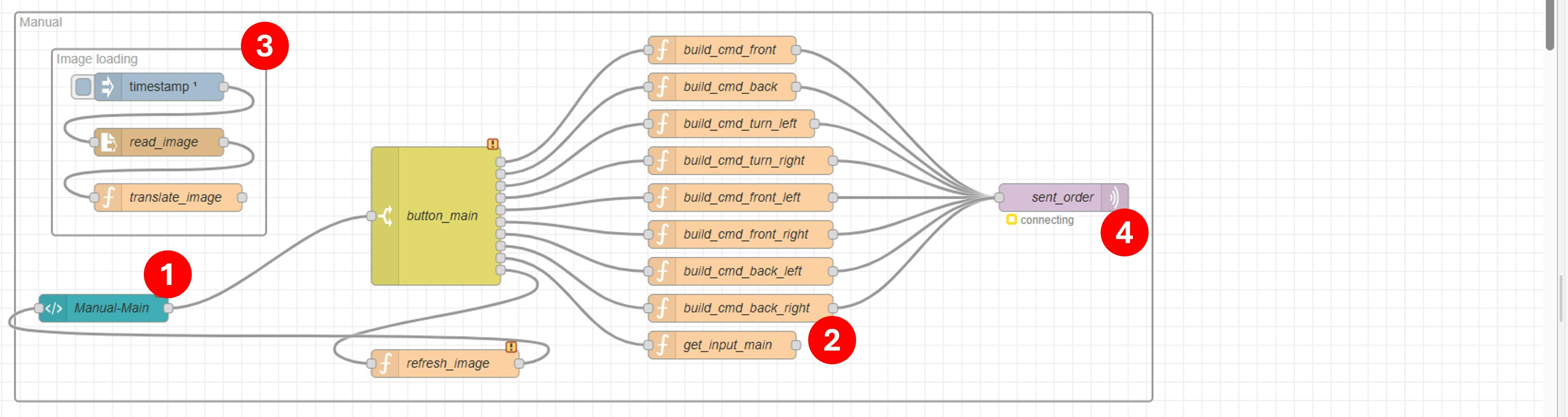
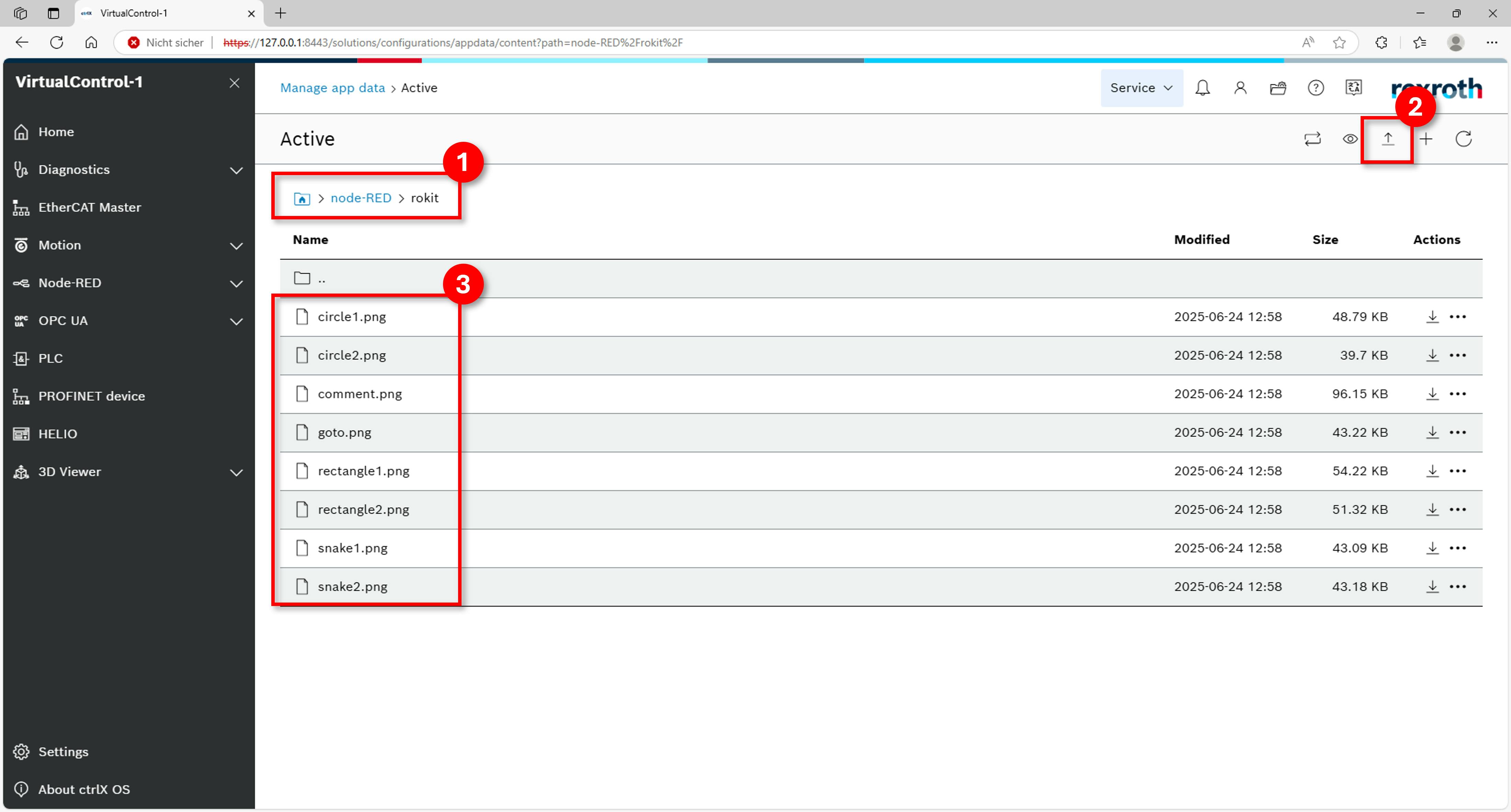
Flow: Route page group Manual: : This group contains the graphical interface for the Manual page and all functions on it. The template node (1) is used to write the main frame interface in the middle of the page. This contains several text boxes and buttons. The function nodes (2) named build are similar to those in comm and are used to construct different commands. There is a subgroup here for loading images saved locally on the Core. Note that all illustrations need to be manually uploaded to the specified location in Core. The specific steps are as shown below. In addition, there is only one MQTT sender node and no receiver node, because we don't need feedback from Navigator here.
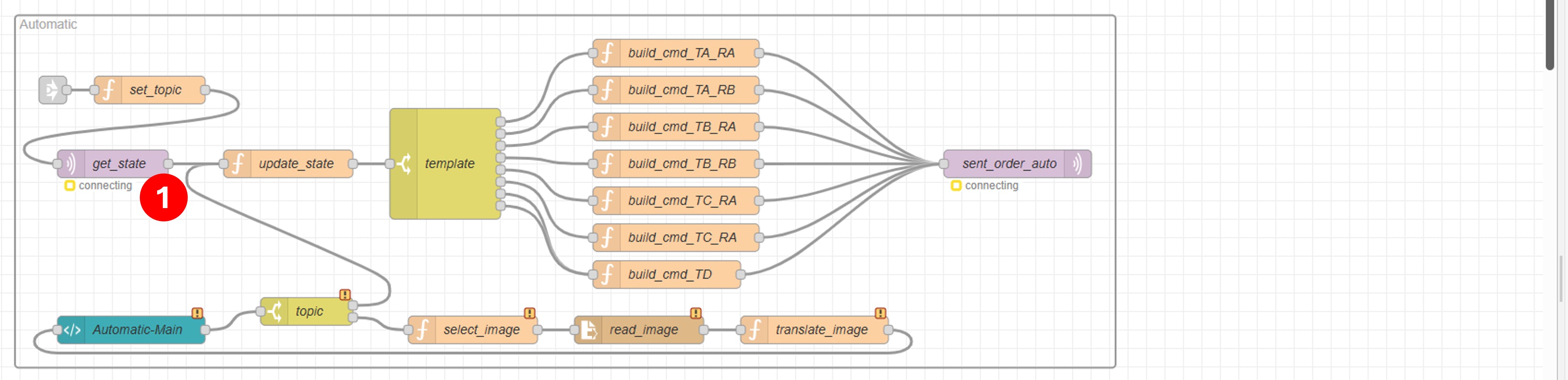
Automatic:On this page, there are also some illustrations loaded locally to show the trajectory templates. Please refer to the Manual section for specific steps. The template node and function nodes with HTML and JavaScript are similar to those in Manual. The difference is that there is an MQTT receiving node (1) to obtain status feedback from Navigator. Before sending the automatic tracking command, it is necessary to determine whether the AGV has completed the previous command.
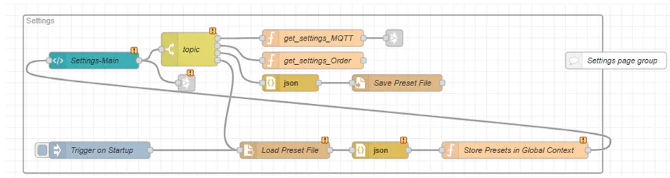
Settings: This page contains settings related to MQTT and commands. The existing content is for reference only, and users can add other global settings.
Apply
There are two application scenarios for this dashboard: the first is running on the physical Core of the AGV, and the second is running on the virtual Core of the PC. Different usage scenarios correspond to different parameter settings. This tutorial only introduces the general application steps on Core and does not involve the parameter settings of the physical AGV or the use of simulation software.
Download and unzip the attachment, which contains a JSON file and some PNG images.
Connect to Core and open the device-dashboard in your browser. If you can’t find Node-RED in the Navigation bar, please go to Settings>Apps to install it. If this is your first time using Node-RED on Core, please watch another tutorial first.
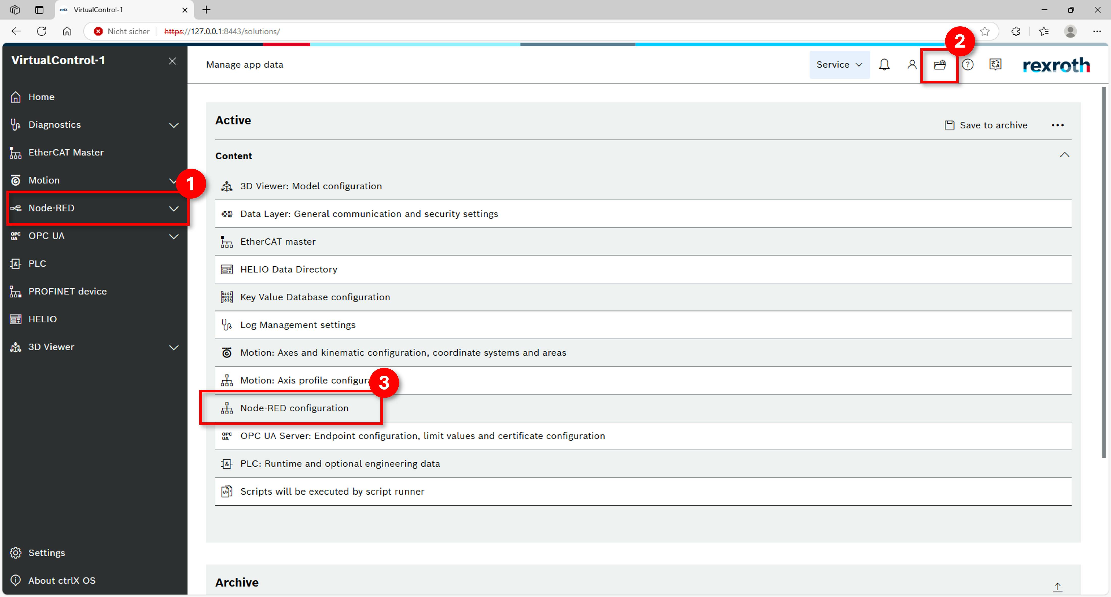
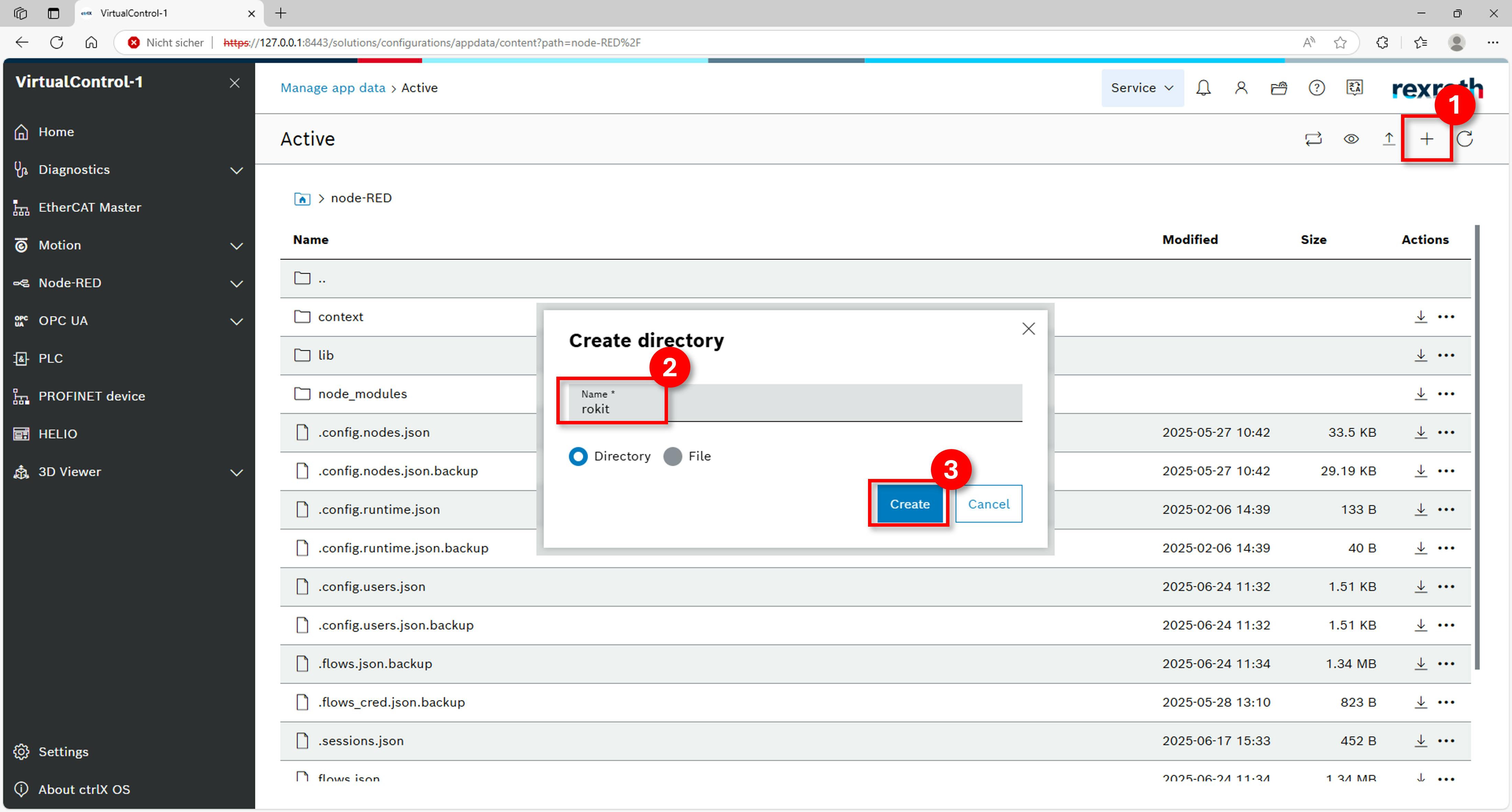
Upload the illustration to Core first. Click the button Manage app data > Node-RED Configuration.
Step 3.1: Find the root of Node-RED on Core Then create a new folder called “rokit” with “+” button.
Step 3.2: Create a new folder Go into folder “rokit” and upload all images from step 1.
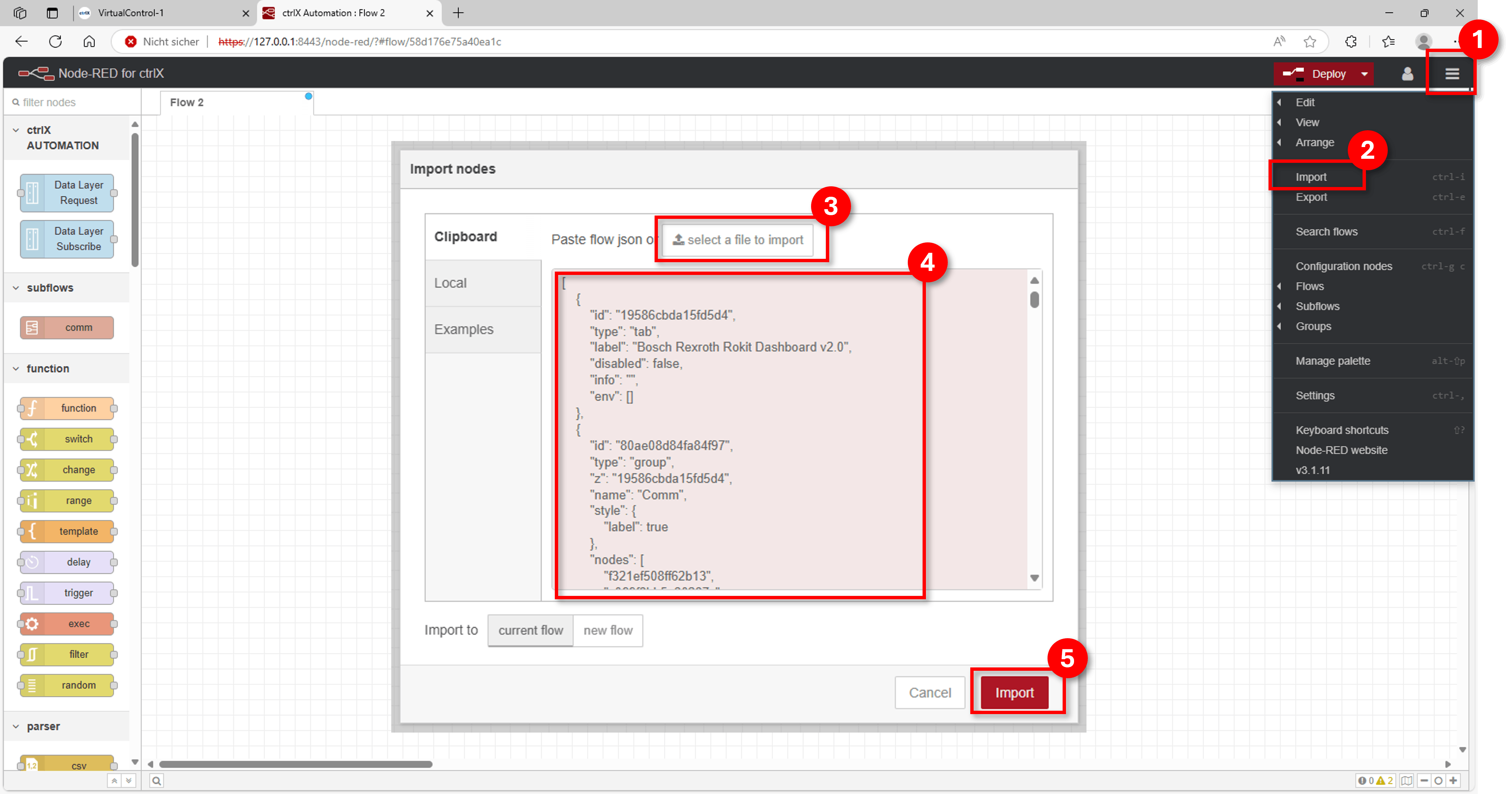
Step 3.3: Upload images Open Node-RED > Flow Editor and click the menu button in the upper right corner and click Import. Then click the button “select a file to import”, find the JSON file from the first step and upload it. Finally, click import.
Step 4: Open Node-Red and import the flow Now you will see the complete project in the current flow. At this point, you will find that there are errors in the Init group. Because you haven't installed the MQTT Broker node yet. If you have already run a broker on your AGV, then just delete this node here. If you want to use it in Node-RED, click “menu button > Manage palette”, then search for “node-red-contrib-aedes” and install it.
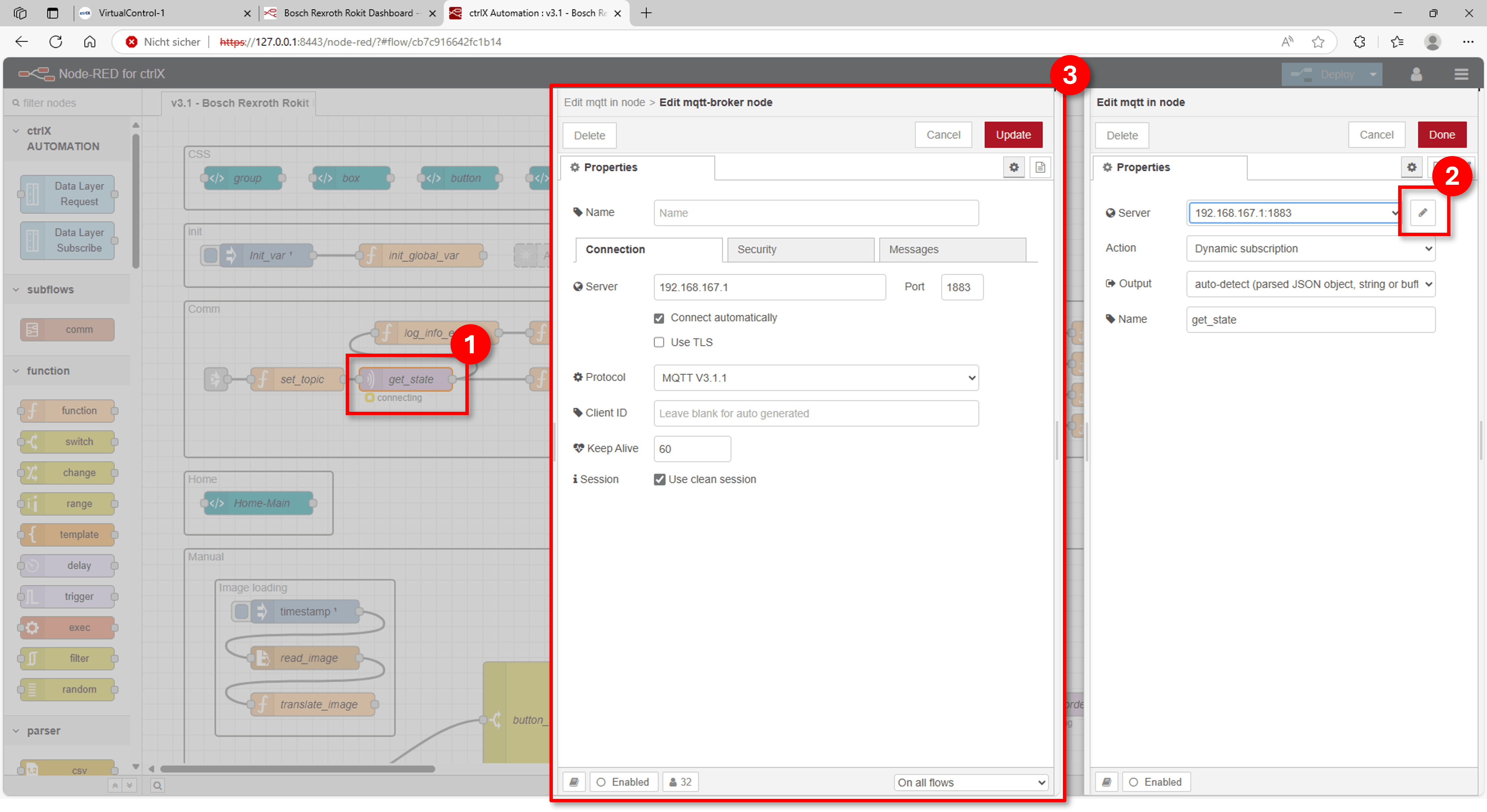
Step 5: Install MQTT broker node or delete it At this point, you will no longer see errors and warnings can be ignored. Select any MQTT send or receive node, double-click it, and then click the Edit button in the Server column of the editing window. On this page, you can fill in the correct “IP address” and “Port” according to your broker settings. After modification, click Update and Done. If a green “connected” appears under the MQTT node, it means you have successfully set up the MQTT connection
Step 6: Modify MQTT server settings Click the “Deploy” button in the upper right corner to complete the compilation of the project. Then go back to “device-dashboard” of the Core, click the button “Dashboard” under “Node-RED”. Now you will see the ROKIT-Dashboard
Before you start using it, you need to complete the general settings about MQTT and VDA 5050 commands on the settings page. After setting all items correctly, click “Save All”. At this time, you will see the position feedback from the AGV in the Output window. If not, it means that the MQTT connection was not established successfully. Please check the relevant settings. The applied settings are stored on the Core and restored automatically after every Node-RED restart or deploy, so this step is only required once.
Step 8: Modify general settings first Finally, you can go to the Manual or Automatic page to operate your AGV. For detailed usage, please refer to the comment box on the page.
Safety notice
The Manual, Automatic and Route pages send real motion commands to the vehicle. Before sending any command, make sure that the area around the AGV is clear and that an emergency stop is within reach. Always check the speed and deviation parameters before confirming.
Troubleshooting
Localized stays red: check the Topic State setting and make sure the ROKIT Navigator is running.
Localized is green but the AGV does not execute orders: check the Topic Order setting. The Info box shows the topic each order was sent to.
Locator responseCode 11: check the Locator session and the map name.
No green “connected” under the MQTT nodes: check the IP address and port in the mqtt-broker configuration node (see step 6).
Images missing on the Manual or Automatic page: upload the PNG files to the rokit folder (see step 3).
Notice: This project is only a sample for reference, and some functions are still defective. If you have any questions or suggestions, please leave a comment to discuss.